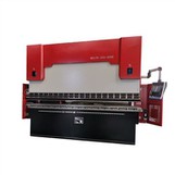
As a trusted supplier of small press brakes, I often encounter customers curious about how the hydraulic system in these machines operates. Understanding the working principles of the hydraulic system in a small press brake is crucial for both operators and those considering purchasing one. In this blog post, I'll delve into the details of how the hydraulic system functions in a small press brake, highlighting its components, operation process, and benefits.
Components of the Hydraulic System in a Small Press Brake
The hydraulic system in a small press brake consists of several key components, each playing a vital role in the machine's operation.
Hydraulic Pump
The hydraulic pump is the heart of the hydraulic system. It is responsible for converting mechanical energy into hydraulic energy by creating a flow of pressurized hydraulic fluid. In a small press brake, the pump is typically driven by an electric motor. There are different types of hydraulic pumps, such as gear pumps, vane pumps, and piston pumps. Gear pumps are commonly used in small press brakes due to their simplicity, reliability, and cost - effectiveness. They work by meshing two gears together, which creates chambers that trap and move the hydraulic fluid from the inlet to the outlet, generating pressure.
Hydraulic Cylinders
Hydraulic cylinders are another essential component. They convert the hydraulic energy from the pump into linear mechanical force. In a small press brake, one or more hydraulic cylinders are used to move the ram (the upper part of the press brake that applies force to bend the sheet metal). The cylinder consists of a piston, a rod, and a cylinder barrel. When pressurized hydraulic fluid enters one side of the cylinder, it pushes the piston, causing the rod to extend or retract. This linear motion of the rod is then transferred to the ram, enabling it to move up and down.
Valves
Valves are used to control the flow, pressure, and direction of the hydraulic fluid in the system. There are several types of valves in a small press brake's hydraulic system:
- Directional Control Valves: These valves determine the direction of the hydraulic fluid flow, allowing the ram to move up or down. They can be manually operated or electrically controlled, depending on the design of the press brake.
- Pressure Control Valves: Pressure control valves are used to regulate the pressure in the hydraulic system. They ensure that the pressure does not exceed the safe operating limit of the machine, protecting both the hydraulic components and the operator. Relief valves are a common type of pressure control valve. They open when the pressure in the system reaches a pre - set level, diverting the excess fluid back to the reservoir.
- Flow Control Valves: Flow control valves regulate the speed of the hydraulic fluid flow, which in turn controls the speed of the ram's movement. This is important for achieving accurate and consistent bending results.
Hydraulic Reservoir
The hydraulic reservoir stores the hydraulic fluid. It also provides a place for the fluid to cool and for contaminants to settle. The reservoir is usually made of steel or plastic and has a sufficient capacity to hold the required amount of hydraulic fluid for the proper operation of the press brake. It is equipped with a filler cap, a sight glass to monitor the fluid level, and a drain plug for maintenance.
Filters
Filters are used to remove contaminants such as dirt, metal particles, and water from the hydraulic fluid. Clean hydraulic fluid is essential for the proper functioning and longevity of the hydraulic components. There are different types of filters in the system, including suction filters, pressure filters, and return filters. Suction filters are located at the inlet of the pump to prevent large particles from entering the pump, while pressure filters are installed in the high - pressure lines to remove smaller contaminants. Return filters are placed in the return line to clean the fluid before it enters the reservoir.
Operation Process of the Hydraulic System in a Small Press Brake
The operation of the hydraulic system in a small press brake can be divided into several steps:


Fluid Intake
The process starts with the hydraulic pump drawing hydraulic fluid from the reservoir through the suction line. The suction filter on the suction line ensures that the fluid entering the pump is free of large contaminants. As the pump operates, it creates a vacuum at the inlet, which causes the fluid to flow into the pump.
Pressure Generation
Once the fluid is inside the pump, the pump's mechanical action pressurizes it. The pressurized fluid is then discharged from the pump into the pressure line. The pressure of the fluid is determined by the pump's design and the load on the system. The pressure control valves monitor and regulate the pressure to ensure it remains within the safe operating range.
Fluid Distribution
The pressurized hydraulic fluid is directed to the directional control valve. Based on the operator's input (either manually or through an electrical control system), the directional control valve determines whether the fluid should be sent to the upper or lower chamber of the hydraulic cylinder. If the operator wants to lower the ram, the valve directs the fluid to the upper chamber of the cylinder. If the ram needs to be raised, the valve sends the fluid to the lower chamber.
Ram Movement
When the pressurized fluid enters the appropriate chamber of the hydraulic cylinder, it pushes the piston, causing the rod to move. This linear motion of the rod is transferred to the ram, which moves up or down accordingly. The speed of the ram's movement is controlled by the flow control valves, which regulate the rate of fluid flow into the cylinder.
Fluid Return
After the ram has completed its movement, the hydraulic fluid in the cylinder needs to return to the reservoir. The directional control valve is adjusted to allow the fluid to flow back through the return line. The return filter in the return line cleans the fluid before it re - enters the reservoir, ensuring that the fluid remains clean for the next operation.
Benefits of the Hydraulic System in a Small Press Brake
The hydraulic system offers several advantages in a small press brake:
High Force Output
Hydraulic systems can generate a large amount of force with relatively small components. This allows small press brakes to bend thick and hard sheet metals effectively. The force generated by the hydraulic cylinders can be precisely controlled, enabling accurate bending of different materials and thicknesses.
Smooth and Precise Operation
The hydraulic system provides smooth and continuous movement of the ram. The flow and pressure control valves ensure that the ram moves at a consistent speed and applies a uniform force, resulting in high - quality bending results. This precision is essential for producing parts with tight tolerances.
Safety
The pressure control valves in the hydraulic system protect the machine from over - pressurization, reducing the risk of damage to the hydraulic components and the press brake itself. Additionally, the system can be designed with safety features such as emergency stop valves, which can quickly stop the ram's movement in case of an emergency.
Versatility
Small press brakes with hydraulic systems can be used for a wide range of bending applications. They can be adjusted to different bending angles and depths, making them suitable for various industries, including automotive, aerospace, and metal fabrication.
Conclusion
In conclusion, the hydraulic system in a small press brake is a complex yet efficient mechanism that plays a crucial role in the machine's operation. By understanding its components, operation process, and benefits, operators can make the most of their small press brakes, ensuring high - quality bending results and long - term reliability.
If you're in the market for a small press brake, we offer a variety of options to meet your needs. Our Small Electric Press Brake Machine is a great choice for those looking for a compact and efficient solution. For more advanced features and precision, our CNC Steel Sheet Press Brake Machine is an excellent option. And if you prefer a hydraulic - powered machine, our Hydraulic Sheet Bending Machine provides the power and performance you need.
If you have any questions or would like to discuss your specific requirements, please don't hesitate to contact us. We're here to help you find the perfect small press brake for your business.
References
- Oberg, E., Jones, F. D., Horton, H. L., & Ryffel, H. H. (2000). Machinery's Handbook: A Reference Book for the Mechanical Engineer, Designer, Manufacturing Engineer, Draftsman, Toolmaker, and Machinist. Industrial Press Inc.
- Spotts, M. F. (1985). Design of Machine Elements. Prentice - Hall.